2026 Author: Erin Ralphs | ralphs@carsalmanac.com. Last modified: 2025-01-22 21:14:09
The fuel consumption monitoring system allows not only to exclude unauthorized refueling and unloading of fuel in companies with their own vehicle fleet. The complex use of technical methods with the use of satellite navigation systems finds application in the constant monitoring of the situation along the route of the car and at the sites of automatic filling stations. Control room operators can remotely track the position of subordinate vehicles on the ground with a high degree of accuracy. For them, readings of fuel consumption sensors and its level in fuel tanks at any time become available.
Used control devices
The fuel control system allows you to identify and prevent the facts of irrational use of the vehicle. These include excess driver speed, deviation from a given route, increased consumptionfuel due to excess weight load. The results obtained by the electronic control units (ECU) and transmitted to the dispatching centers via GLONASS/GPS vehicle trackers make it possible to analyze the technical condition of the vehicle and its operating conditions.

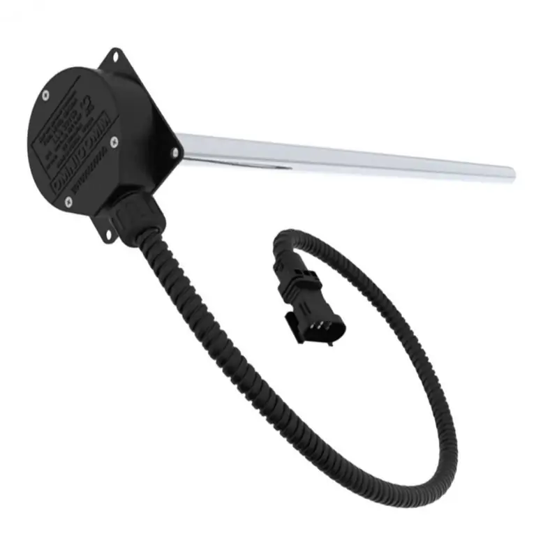
Sensitive elements of fuel control sensors use different principles for determining its quantity. They can be divided into several main groups:
- level meters used to constantly determine the percentage of fuel remaining in the tank relative to its maximum value at the current time;
- sensors of a discrete type, which are signaling devices for reaching the fuel level of fixed values set by the adjustment elements;
- fuel meters that determine the instantaneous fuel consumption of a car engine.
The first two types of sensors are placed in the fuel tanks of cars. The flowmeters are installed in the pipelines of the fuel system lines. They are part of the on-board equipment of the fuel control system. Measurement accuracy can be improved by sharing the readings of different types of meters.
Measurement methods
To control the fuel level and its consumption, contact methods are used, in which the elements of the measuring sensor directly interact with the fuel medium in which it is placed. The following types of sensors are most commonly used:
- mechanicalfloat level meters, the output signal of which is the changing resistance of the rheostat;
- float level switches with magnetically sensitive metal contacts;
- capacitive level sensors;
- turbine type flow sensors.
The listed sensitive sensors are an integral part of the on-board electronic measurement circuit, the signal of which in analog or digital form is subsequently used to register in the vehicle's ECU. Flight recorder information is transmitted via GLONASS/GPS communication channels to the main terminal of the dispatcher's transport control system.
Mechanical float meters
The sensitive element of this type of sensor is a light float that takes its position on the surface of the fuel in the tank. A system of mechanical transmission links connects it to the moving contact of a rheostat fixed at the bottom of the tank.

The changing resistance is the arm of the measuring bridge. The current indicator is included in the measuring diagonal of the resistance bridge.
With a minimum amount of fuel, the float moves the movable contact through the lever system to a position where the bridge is balanced. The current in the measuring diagonal does not flow and the fuel level readings of the device are close to zero. As the fuel tank fills, the float tracks the position of the upper level, while moving the movable contact of the rheostat.
This causes bridge imbalanceresistance and current flow through the measuring instrument. The arrow of the device moves along the scale towards its maximum value.
Float switches
The signal at the output of such a sensor, which has a discrete value, warns of the fuel level in the tank reaching certain fixed values. The actuating elements of the sensor are magnetically sensitive reed switches, which are insulated glass bulbs with high-conductivity metal contacts placed in them.
A light float with a small permanent magnet built into its body moves along a vertical guide rigidly fixed in the fuel tank. On the inner surface of the guide, isolated from the fuel in the tank, signaling devices are fixed at different heights, the contacts of which close (or open) when the float's permanent magnet enters the magnetic field.
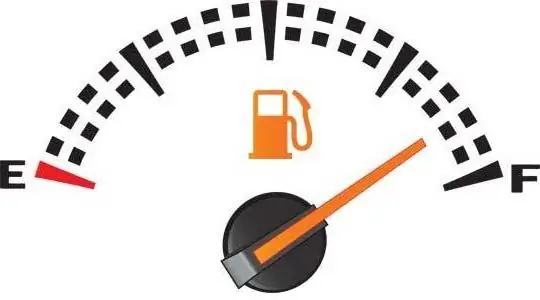
Their signals are fixed by an electronic circuit. The scale of the instrument of the fuel level indicator installed in the cab of the vehicle is made in the form of values (¼, ½, ¾) of the part of filling the fuel tank. Its full filling corresponds to the mark "F" (Full), located in the extreme right position on the scale of the device.

At the same time, the reed relay signals are used by the vehicle's ECU to form a complex signal transmitted by the GLONASS/GPS tracker to the server connected to the dispatcher's terminal.
Capacitive level sensors
Property of a capacitorchange the value of its electrical capacitance depending on the dielectric constant of the material that fills the space between its plates, is used in meters with capacitive-type sensors.

Such sensors are coaxial type capacitors. Their facings are made in the form of hollow cylinders of different diameters, having a common vertical axis. The free space between them with empty tanks fills with air. In the process of refueling, its level between the capacitor plates rises, thereby changing the value of the total permittivity of the dielectric material. The capacitance of the coaxial capacitor of the sensor included in the circuit of the oscillatory circuit of the electronic circuit changes. This results in a change in its resonant frequency, which is monitored by the frequency/voltage converter.

The display circuit generates a value proportional to the degree of filling of the fuel tank at the current time.
Fuel flow sensors
Turbine measurement method is most commonly used in fuel consumption monitoring systems. It is based on the dependence of the speed of rotation of the impeller (turbine), located in the pipeline of the fuel system of the car, on the flow rate of the liquid flowing through it.

The impeller is fixed on the body of a permanent magnet (rotor), the rotation of which leads to the appearance of a changing electromagnetic flux in the stationary stator winding,located on the walls of the pipeline. The AC voltage is converted to DC voltage, which is sensed by the electronic circuit. The instantaneous consumption determines the speed of rotation of the turbine, and the fuel consumption for a certain time is calculated by the ECU based on the number of revolutions during this time. The unit of measure used in fuel control systems is the amount of fuel used to cover a certain distance. Most often, the efficiency of a car is determined by fuel consumption per 100 kilometers (l/100 km.)
Conclusion
The fuel consumption monitoring system is an integral part of the overall system for monitoring the operation of vehicles through the integrated use of various technical means. Using the data obtained, it is possible to develop fuel consumption rates for the routes most often used for road transportation by a transport company. Such control also helps to prevent or minimize the theft of gasoline and diesel fuel. Unfortunately, fuel quality control can only be carried out in company laboratories using special equipment.
Recommended:
Why increased fuel consumption? Causes of increased fuel consumption

A car is a complex system where each element plays a huge role. Almost always, drivers face various problems. For some, the car drives to the side, others experience problems with the battery or exhaust system. It also happens that fuel consumption has increased, and suddenly. This puts almost every driver in a stupor, especially a beginner. Let's talk in more detail about why this happens and how to deal with such a problem
Fuel: consumption rate. Consumption rates of fuels and lubricants for a car

In a company where vehicles are involved, it is always necessary to take into account the cost of their operation. In the article, we will consider what expenses should be provided for fuels and lubricants (POL)
Cooling system device. Branch pipes of the cooling system. Replacing the pipes of the cooling system

The internal combustion engine works stably only under a certain thermal regime. Too low a temperature leads to rapid wear, and an excessively high temperature can cause irreversible consequences, up to jamming of the pistons in the cylinders. Excess heat from the power unit is removed by the cooling system, which can be liquid or air
Car air conditioning system: diagnostics, repair, flushing, cleaning, system pressure. How to flush a car's air conditioning system?

The warm season is accompanied by frequent requests from car owners to service shops for such a service as diagnostics of the car's air conditioning system, as well as troubleshooting. We will understand the reasons for this phenomenon
Efficient cars in terms of fuel consumption in Russia. Fuel Economy Cars: Top 10

In a crisis, it is advisable to save everyone and everything. This can be applied to cars as well. It has long become clear to car owners and manufacturers that it is possible and necessary to save money primarily on fuel

