2026 Author: Erin Ralphs | [email protected]. Last modified: 2025-01-22 21:14:18
The schemes of engine cooling systems are almost identical on all machines. Modern cars use a hybrid system. Yes, it is, because not only liquid, but also air is involved in cooling. They blow the radiator cells. Due to this, cooling is much more efficient. It is no secret that at low speeds, the circulation of the liquid does not save - you have to additionally install a fan on the radiator.
Radiator fan

Let's talk about domestic cars, for example, the Lada. To ensure better heat transfer, the engine cooling system ("Kalina"), the circuit of which has a standard configuration, contains a fan. Its main function is to blow air into the radiator cells when the liquid reaches a critical temperature. Operation is controlled by a sensor. On domestic cars, it is installed at the bottom of the radiator. In other words, there isliquid that gives off heat to the atmosphere. And it should have a temperature of 85-90 degrees at this point of the contour. If this value is exceeded, it is necessary to carry out additional cooling, otherwise boiling water will enter the engine jacket. Consequently, the operation of the motor will occur at critical temperatures.
Cooling radiator

It serves to release heat into the atmosphere. The liquid passes through the cells, which have narrow channels. All these cells are connected by thin plates that improve heat transfer. When moving at high speed, the air passes between the cells and contributes to the rapid achievement of the result. This element contains any circuit of the engine cooling system. Volkswagen, for example, is no exception.
Above was considered a fan that is mounted on a radiator. It blows air when a critical temperature is reached. To improve the efficiency of the element, it is necessary to monitor the cleanliness of the radiator. Its cells are clogged with debris, heat transfer is deteriorating. Air does not pass well through the cells, heat is not released. The result - the temperature of the engine rises, its operation is disturbed.
System thermostat

It's nothing but a valve. It reacts to temperature changes in the cooling circuit. More about them will be discussed below. The scheme of the UAZ engine cooling system is based on the use of a high-quality thermostat, which is made ofbimetallic plate. Under the action of temperature, this plate is deformed. You can compare it with a circuit breaker used in the power supply of houses and enterprises. The only difference is that it is not the switch contacts that are controlled, but the valve that supplies hot liquid to the circuits. The design also has a return spring. When the bimetallic plate cools down, it returns to its original position. And the spring helps her to return.
Sensors used in refrigeration

Only two sensors are involved in the work. One is mounted on the radiator, and the second is in the jacket of the engine block. Let's go back to domestic cars and remember the Volga. The engine cooling system circuit (405) also has two sensors. Moreover, the one that is located on the radiator has a simpler design. It is also based on a bimetallic element, which deforms with increasing temperature. This sensor activates the electric fan.
On cars of the classic VAZ series, a direct fan drive was previously used. The impeller was installed directly on the axis of the pump. The rotation of the fan was made constantly, regardless of the temperature in the system. The second sensor, installed in the engine jacket, serves one purpose - transmitting a signal to the temperature indicator in the cabin.
Fluid Pump

Let's get back to the Volga. Cooling systemengine (406), the circuit of which contains a circulation liquid pump, cannot simply function without it. If you do not give the fluid movement, then it will not be able to move along the contours. Consequently, stagnation will appear, antifreeze will begin to boil, and the motor may jam.
The design of the liquid pump is very simple - aluminum body, rotor, drive pulley on one side and plastic impeller on the other. Installation is made either inside the engine block or outside. In the first case, the drive is carried out, as a rule, from the timing belt. For example, on VAZ vehicles, starting from model 2108. In the second case, the drive is carried out from the crankshaft pulley.
Stove outline

Some cars made decades ago had air-cooled engines. There is only one inconvenience in this case: I had to use a gasoline stove, which “ate” a lot of fuel. But if liquid circuits of engine cooling systems are used, you can take hot antifreeze, which is supplied to the radiator. Thanks to the stove fan, hot air is supplied to the passenger compartment.
In all cars, the stove radiator is mounted under the instrument panel. First, an electric fan is installed, then a radiator is installed on it, and air ducts fit on top. They are necessary for the distribution of hot air throughout the cabin. In new cars, its distribution is controlled by microprocessor systems and stepper motors. They open or closedampers depending on the temperature in the cabin.
Expansion tank
Everyone knows that any liquid expands when heated - increases in volume. So it needs to go somewhere. But on the other hand, when the liquid cools, its volume decreases, therefore, it must be added to the system again. It is impossible to do this manually, but with the help of an expansion tank, this procedure can be automated.
Most modern cars use sealed-type engine cooling systems. For these purposes, a plug with two valves is provided on the expansion tank: one for the inlet, the second for the outlet. This allows the pressure in the system to be close to one atmosphere. With a decrease in its indicator, air is sucked in, with an increase, it is discharged.
Cooling pipes

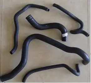
To ensure fluid circulation, the engine cooling circuits contain rubber pipes. With their help, fluid is transferred between nodes. The tube is a rubber tube. Inside it has reinforcement, which increases the strength of the product. The pipes have different lengths and shapes. These parameters depend on the car model.
The nozzles are fastened with metal worm-type clamps. To ensure maximum impermeability, silicone sealants can be used. It is reasonable to use them in the case when there aresmall defects. Thanks to the sealant, all irregularities are filled. When operating a car, it is necessary to carefully monitor the condition of the pipes. Cracks are not allowed, otherwise fluid will leak and the system will not seal.
Conclusions
After a thorough analysis, you can see that the scheme of the engine cooling system, despite the configuration, is the same on all cars. For efficient operation of the system, it is necessary to monitor the status of all its elements. Not only a thermostat failure, but even a valve malfunction in the expansion tank cap can cause the coolant temperature to rise. Therefore, it is necessary to carry out maintenance of the system in a timely manner so that at the wrong moment it does not fail. Otherwise, engine malfunction may occur. Excessive overheating of the cylinder block can lead to cracking, as well as jamming of the piston group.
Recommended:
Cooling system device. Branch pipes of the cooling system. Replacing the pipes of the cooling system

The internal combustion engine works stably only under a certain thermal regime. Too low a temperature leads to rapid wear, and an excessively high temperature can cause irreversible consequences, up to jamming of the pistons in the cylinders. Excess heat from the power unit is removed by the cooling system, which can be liquid or air
Car: how it works, the principle of operation, characteristics and schemes. How does a car muffler work?

Since the creation of the first gasoline-powered car, which happened more than a hundred years ago, nothing has changed in its main parts. The design has been modernized and improved. However, the car, as it was arranged, remained as such. Consider its general design and arrangement of some individual components and assemblies
Car engine cooling system: device and principle of operation

The engine cooling system in the car is designed to protect the working unit from overheating and thereby controls the performance of the entire engine block. Cooling is the most important function in the operation of an internal combustion engine
Engine cooling fan. Engine cooling fan repair

When the engine cooling fan fails, it is urgent to change it. That is, remove, disassemble, repair and install back. This article shows you how to do it yourself
Ways of strapping and slinging schemes for goods. GOST: cargo slinging schemes

Cargo transportation is a very complex process. Many, for example, do not think that there are dozens of ways to strap and sling cargo

