2026 Author: Erin Ralphs | ralphs@carsalmanac.com. Last modified: 2025-01-22 21:14:11
The use of thyristor-based chargers is justified - the recovery of the batteries is much faster and "more correct". The optimal value of the charging current, voltage is maintained, so it is unlikely that it will be possible to harm the battery. After all, electrolyte can boil away from overvoltage, lead plates can collapse. And all this leads to the failure of the battery. But you need to remember that modern lead-acid batteries can withstand no more than 60 full discharge and charge cycles.
General description of the charger circuit
Everyone can make thyristor chargers with their own hands if they have knowledge in electrical engineering. But in order to do all the work correctly, you need to have at least the simplest measuring device on hand - a multimeter.
It allows you to measure voltage, current, resistance, check the performance of transistors. And in the charger circuit there are such functional blocks:
- Downdevice - in the simplest case, this is an ordinary transformer.
- The rectifier unit consists of one, two or four semiconductor diodes. A bridge circuit is usually used, as it can be used to obtain almost pure direct current without ripple.
- A filter block is one or more electrolytic capacitors. With their help, the entire variable component in the output current is cut off.
- Voltage stabilization is performed using special semiconductor elements - zener diodes.
- Ammeter and voltmeter control current and voltage, respectively.
- The output current parameters are adjusted by a device assembled on transistors, a thyristor and a variable resistance.
The main element is a transformer
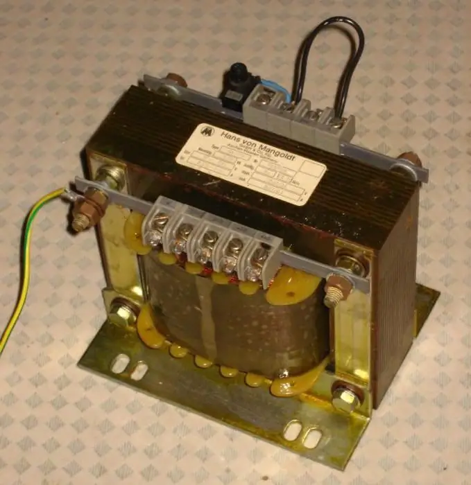
Without it, it’s just nowhere, it’s impossible to make a charger with regulation on a thyristor without using a transformer. The purpose of using a transformer is to reduce the voltage from 220 V to 18-20 V. This is how much is needed for the normal operation of the charger. General design of the transformer:
- Magnetic core made of steel plates.
- Primary winding connected to AC 220V.
- The secondary winding is connected to the main charger board.
In some designs, two secondary windings connected in series can be used. But in the design discussed in the article, a transformer is used, which has one primary and the same number of secondary windings.
Roughcalculation of transformer windings
It is advisable to use a transformer with an existing primary winding in the design of a thyristor charger. But if there is no primary winding, you need to calculate it. To do this, it is enough to know the power of the device and the cross-sectional area of \u200b\u200bthe magnetic circuit. It is advisable to use transformers with a power of over 50 watts. If the cross section of the magnetic circuit S (sq. cm) is known, you can calculate the number of turns for each 1 V of voltage:
N=50 / S (sq cm).
To calculate the number of turns in the primary winding, you need to multiply 220 by N. The secondary winding is calculated in the same way. But keep in mind that in a household network, the voltage can jump up to 250 V, so the transformer must withstand such drops.
Winding and assembly of the transformer
Before you start winding, you need to calculate the diameter of the wire that you want to use. To do this, use a simple formula:
d=0.02×√I (windings).
The cross section of the wire is measured in millimeters, the winding current is in milliamps. If you need to charge with a current of 6 A, then substitute the value of 6000 mA under the root.
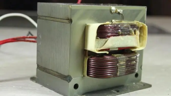
Having calculated all the parameters of the transformer, start winding. Lay the coil to coil evenly so that the winding fits in the window. Fix the beginning and end - it is advisable to solder them to free contacts (if any). As soon as it's readywinding, it is possible to assemble transformer steel plates. Be sure to varnish the wires after winding is completed, this will get rid of the buzz during operation. The core plates can also be treated with an adhesive solution after assembly.
PCB manufacturing
To make your own thyristor car battery charger circuit board, you need to have the following materials and tools:
- Acid for cleaning the surface of foil material.
- Solder and tin.
- Foil textolite (getinax is harder to get).
- Small drill and 1-1.5 mm drill bits.
- Ferric chloride. It is much better to use this reagent, as it removes excess copper much faster.
- Marker.
- Laser printer.
- Iron.
Before you start editing, you need to draw tracks. It is best to do this on a computer, then print the picture on a printer (necessarily laser).
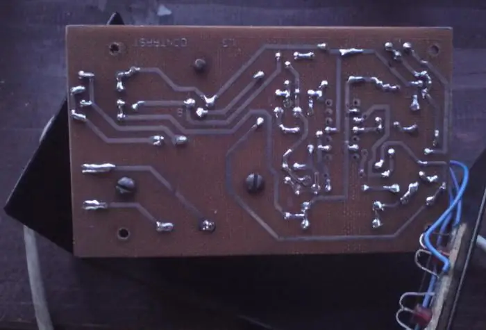
Printing should be carried out on a sheet from any glossy magazine. The drawing is translated very simply - the sheet is heated with a hot iron (without fanaticism) for several minutes, then it cools down for a while. But you can also draw paths by hand with a marker, and then place the textolite in a solution of ferric chloride for several minutes.
Assignment of memory elements
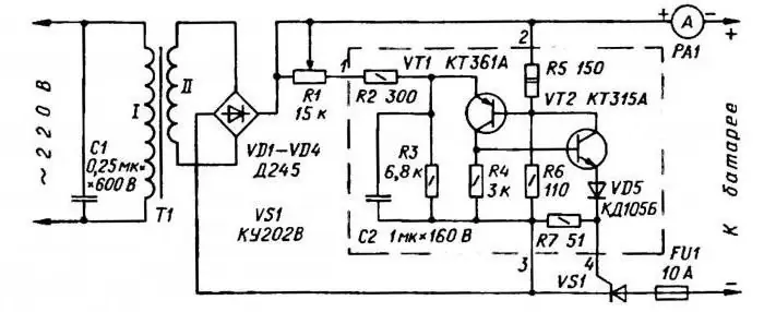
A device based on a phase-pulse controller on a thyristor is being implemented. It does not contain scarce components, therefore, provided thatyou will mount serviceable parts, the whole circuit will be able to work without tuning. The design contains the following elements:
- Diodes VD1-VD4 is a bridge rectifier. They are designed to convert AC to DC.
- The control unit is assembled on unijunction transistors VT1 and VT2.
- The charging time of the capacitor C2 can be adjusted by the variable resistance R1. If its rotor is shifted to the extreme right position, then the charging current will be the highest.
- VD5 is a diode designed to protect the thyristor control circuit from reverse voltage that occurs when turned on.
This scheme has one big drawback - large fluctuations in the charging current if the network voltage is unstable. But this is not a hindrance if a voltage stabilizer is used in the house. You can assemble a charger on two thyristors - it will be more stable, but it is more difficult to implement this design.
Mounting elements on a printed circuit board
It is advisable to mount diodes and thyristor on separate radiators, and be sure to isolate them from the case. All other elements are installed on the printed circuit board.
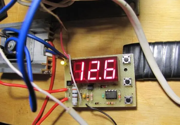
It is undesirable to use hanging mounting - it looks too ugly, and dangerous. To place elements on the board, you need:
- Drill holes for the legs with a thin drill.
- Tin all print tracks.
- Coat the tracks with a thin layer of tin, this will ensure the installation is secure.
- Install allelements and solder them.
After installation is complete, you can cover the tracks with epoxy or varnish. But before that, be sure to connect the transformer and the wires that go to the battery.
Final assembly of the device
After the installation of the charger on the KU202N thyristor, you need to find a suitable case for it. If there is nothing suitable, make it yourself. You can use thin metal or even plywood. Place the transformer and radiators with diodes, thyristor in a convenient place. They need to be well chilled. For this purpose, you can install a cooler in the back wall.
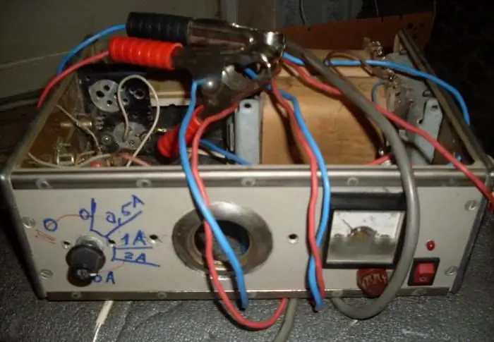
You can even install a circuit breaker instead of a fuse (if the dimensions of the device allow). On the front panel you need to place an ammeter and a variable resistor. Having assembled all the elements, proceed to test the device and its operation.
Recommended:
The best batteries for a car: review, reviews. The best battery charger
When car enthusiasts think about choosing a battery for their car, the first thing they look at is tests conducted by independent experts and various specialized agencies. However, the results show that even with the same parameters declared by manufacturers, products of different brands can have the same different characteristics. Everyone wants to buy the best battery and therefore you need to know how to choose it
DIY car battery charger is easy to make
Proper battery charging can be performed by specialists in certain services providing this service. But if you do not want to waste your time and money, you can do it yourself. First, remove your battery from the car
Charger "Orion PW325": reviews. Charger "Orion PW325" for cars: instructions
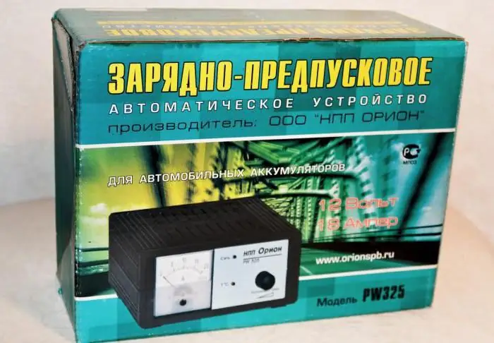
Every self-respecting car enthusiast should have a charger in their arsenal, as well as a spare tire or a set of keys
Pulse charger for car battery: diagram, instructions
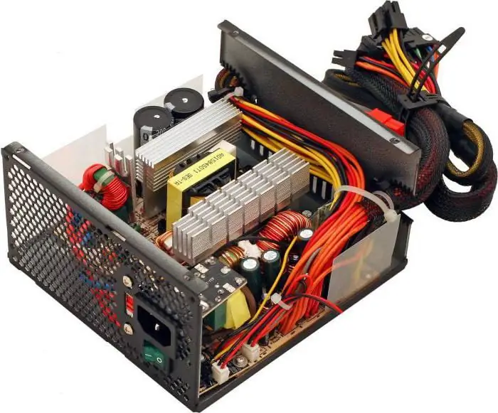
Pulse chargers for car batteries have gained wide popularity. There are quite a few schemes for such devices - some prefer to assemble them from improvised elements, while others use ready-made blocks, for example, from computers. The power supply of a personal computer can be easily converted into a quite high-quality charger for a car battery
Charger "Kedr-Auto 4A": instructions. Charger for car batteries
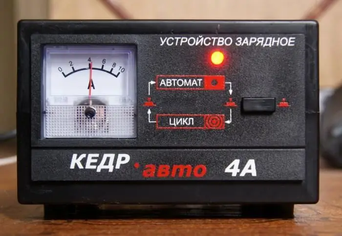
One of the most popular brands of car chargers is "Kedr" - devices of this brand are bought by many vehicle owners

