2026 Author: Erin Ralphs | [email protected]. Last modified: 2025-06-01 05:35:55
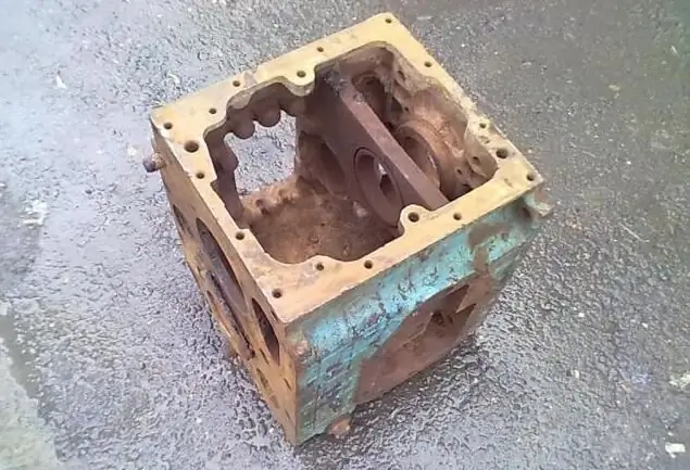
The MTZ-82 gearshift pattern is typical for the Belarus tractor. The unit is designed for 9 forward and 2 reverse speeds with the possibility of doubling their number using a reduction gear. The block has one seat for the bearing, the output shaft does not differ in significant width. Before studying the order of switching speeds, you should familiarize yourself with the device of the mechanism.

Device and gearshift diagram MTZ-82
The assembly under consideration is a set of gears of various types with an injection device. A drive shaft is mounted on the block, a plunger with an oil seal is provided. There is a crankshaft at the bottom of the box. The transmission gears are attached with bushings. The supercharger is responsible for the operation of the shaft, and the neutral gear is engaged by means of a locking mechanism.
The crankshaft is fixed on a pair of supports, linings are used only in the lower compartment of the skeleton. A wide block with two gears is provided in the center of the element. In addition, in the upper part there is a rod fixed on a pair of clamps. The shifter is equipped with a sleeve.
Plunger and stuffing box
The MTZ-82 gearshift scheme includes a plunger, which in this case is equipped with a switch. The blocker has a gearbox, small thickness linings, glasses and plunger discs. The lower part of the mechanism is equipped with a pair of rods, which are fixed by clips.
The stuffing box is mounted above the block, gears are provided on the sides of it. There is a disk in the central part. The stops of the assembly are made with small racks, the operation of the stuffing box is carried out from the gear aggregating with it. The element is connected to the shaft by means of a rod. An adapter and working bushings are installed at the top.

Crankcase and supercharger
The crankcase in the MTZ-82 gearshift scheme is equipped with two gears. The unit is equipped with strong supports and a wide block at the bottom. The equipment has two linings, the glasses are installed in the side segment of the block. They are equipped with wide bushings that are subject to abrasion under heavy load.
The inflation mechanism is discs equipped with low elasticity gaskets. The racks of the part have small protrusions, the lower support is fixed tightly. This assembly must be cleaned regularly as it is prone to clogging with used engine oil.
MTZ-82: shift pattern, shift order
Before starting work, carefully study the scheme. The basic principle of operation of the mode switching system is the use of a step-down gearbox. This allows you to double the number of standard gears to 18 forward positions andfour reverse speeds. When shifting to a lower or higher gear, the clutch disc must be disengaged. To do this, simply depress the transmission pedal to the stop, after which the gearshift control levers are used.

MTZ-82 gearshift pattern (shift order):
- The power unit must be idling.
- Clutch pedal fully depressed.
- The required position is stuck.
- Smoothly pressing the gas, slowly release the clutch pedal.
Beginners may not succeed the first time, and the tractor will stall. In this case, repeat the procedure again.
Notation
The MTZ-82 gearshift diagram is shown below. The work is carried out by two levers (position control element and the second analogue of the reduction gear). The selection of the desired gears and ranges of the gearbox is carried out in accordance with the corresponding positions. First, the 1st or 2nd range is turned on, after which the lever is moved to the neutral position, the further gear is selected.
The reduction gear controller must be activated during the operation of the equipment: the rear position is the accelerating stage (“hare”) or forward in the decelerating position (“tortoise”). It is allowed to hold the gear lever in the neutral position to facilitate starting the motor at negative air temperatures.

1 - intermediate PTO nut. 2 - shaftintermediate type. 3 - main PTO. 4 - driven gear of the reduction PTO. 5 - gearbox housing. 6 - a glass of the rear shaft. 7 - sliding type gear for 4th and 5th gears. 8 - gear of the 3rd range. 9 - slider. 10 - PTO secondary. 11 - ball element. 12 - hatch gearbox.
13 - plug for the bay. 14 - ball bearing. 15 - gearshift lever. 16 - protective cover. 17 - pin element. 18 - frame detail. 19 - roller. 20 - ball switch. 21 - switch. 22 - shims. 23 - corrective seals. 24 - nut. 26 - driving gear. 27/29 - bearings of a conical configuration. 28 - thrust washer.
30 - impeller. 31 - seat of the inner roller. 32 - bushing. 33 - internal shaft. 34 - bearing group. 35 - bushing. 36 - gear 2 stages of the gearbox. 37 - gear 1 stage. 38 - intermediate gear. 39 - bearing. 40 - gear 3 gears. 41 - driven gear element of the 4th range. 42 - reverse gear. 43 - axis. 44 - 5th gear gear. 46 - axis. 47 - gear element of the reduction gear.
Working with reverse gear
The MTZ-82 gearshift scheme of the new model provides for the use of a range control lever and a similar element of a reverse type gearbox for control. The choice of positions and steps is made forward or backward by turning the levers to the appropriate positions. Further operation of the unit is similar to the operation of a gearbox with a reduction gear.

The reducer has a pairsteps, in the first position include the 1st, 3rd, 4th and 5th forward gear or the first speed in the rear direction. The rest of the ranges are activated by the second stage. After the drive gear engages with the outer ring of the output shaft, the first stage is activated. After shifting the gear element back to complete aggregation with the inner crown, the second stage is switched on.
Double gear moves on the input shaft, depending on the stage of the gearbox, and includes 5th or 6th gear (forward), 4th and 7th speed (reverse). The third gear sliding tooth, when moved to the forward position, activates the 5th or 6th position. Moving back, the same part connects the internal tooth of the secondary shaft with the primary counterpart, providing the 9th direct range of the gearbox. Moving the sliding gear back on the drive corresponds to the first and second forward speeds, they are engaged, and moving back contributes to the activation of the reverse gear.
Primary shaft
On the MTZ-82 tractor, the gear shifting scheme provides for the aggregation of the gearbox with the primary power take-off shaft (PTO) of the rear placement. When switching the independent PTO handle to the maximum left position, the synchronizer is activated, to the right position - independent mode, and the middle position - switching on the neutral range.
Engaging the PTO on "Belarus" is allowed only if the handle is set to the position of activation of a synchronous or independent drive. In the neutral position, the input shaft does not function. The control lever has twopositions:
- Switching the handle from the extreme forward position to the rear position contributes to the inclusion of the rear shaft.
- Similar procedure in reverse order disables the PTO.
It is recommended to turn the unit on or off when the engine is running. The control of the secondary semi-independent shaft is carried out using a rod located to the left of the driver's seat. The mechanism also has a pair of fixed positions: top on and bottom off.

48 - roller. 49 - leash. 50 - gear. 51 - fork. 52 - spring ring. 53 - thrust ring. 54 - driven gear. 55 - hatch cover. 56 - driven gear 1 position and reverse. 57 - sliding gear. 58 - shaft.
Checkpoint Maintenance
The MTZ-82 gearshift scheme during maintenance includes control of the gearbox mounting, as well as clutch elements and the main shaft frame. It is also required to regularly check the oil level, replenishing it in a timely manner.
The gearbox oil sump serves as a common bath for the clutch basket compartment and the rear axle housing. In the transmission unit, the oil level should be at the lower mark of the edge of the control hole for the plug. It is located on the right side of the checkpoint.
The equipment is installed on a straight flat area, waiting for the oil to cool down, which flows down the walls. Then check its level and top up if necessary. The filling hole is located on the top of the box lid. When replenishing oil, it is advised to open the drainassembly holes, as well as the clutch basket and the rear axle frame.
If metal impurities or chips are found in the mining, it is necessary to flush the transmission assembly with diesel fuel. This will require about 30 liters of diesel fuel, which is poured into the transmission unit, after which the tractor is started for 5 minutes. Then the diesel fuel is drained, and the oil is replenished to the required level. During operation, it is necessary to observe the appearance of extraneous noises and sounds. Their presence may indicate a malfunction of the bearings of the output shaft of the power take-off or the gear of the front drive of the tractor.

Finally
The MTZ-82 gearbox (diagram, shift photos are presented above) is one of the most important tractor control units. She has many ranges, each of which has its own nuances. For their correct inclusion, certain rules must be observed. This will increase the efficiency of the equipment and the working life of the mechanism.
Recommended:
How to turn off ABS: the order of work. Anti-lock braking system
Almost every modern car has an anti-lock braking system. The main task is to prevent an accident during braking, when the car loses its stability. The device helps the driver to maintain control over the car and reduce the braking distance. Not all drivers liked this system. We have to think about the question of how to turn off the ABS, which is especially often of interest to experienced drivers
Automatic transmission - how to use? Automatic transmission switching and control modes
Today, many novice drivers, and motorists with experience, choose a car with an automatic transmission. Beginners are often afraid of the very need to shift gears while driving, experienced drivers have appreciated the possibilities of calm and measured movement in a car equipped with automatic transmission
Correct shifting - why do you need to learn this?
The article discusses the consequences of improper gear shifting, and also talks about why you need to learn how to shift gears correctly
Rear view camera connection diagram: diagrams, work order, recommendations
The number of cars on the roads is growing exponentially. There are fewer and fewer parking spaces. At the same time, manufacturers are increasing the dimensions of passenger cars, thereby reducing their ability to maneuver in the parking lot. This leads to emergency situations when reversing. Installing a rear view camera on the car will help solve this problem
Why does the car twitch while driving? Reasons why the car twitches at idle, when shifting gears, when braking and at low speeds
If the car twitches while driving, it is not only inconvenient to operate it, but also dangerous! How to determine the cause of such a change and avoid an accident? After reading the material, you will begin to understand your "four-wheeled friend" better

